Tungsten Carbide (Cemented Carbide) Machining for Wear Parts
Cemented carbide is tungsten carbide grains held in a cobalt binder: harder than the tool that would cut it, and finished by grinding, EDM or diamond tooling rather than turned like steel. We make thin strips, plates and profiled wear parts — drilled, slotted and countersunk to the drawing. The route for a given part depends on grade and geometry, so it is agreed before anything is cut, and it is what the quote is built on.
A material that punishes assumptions
What actually decides whether a carbide part comes out right.
Hardness is the point — and the problem
Carbide keeps its shape because it is harder than the tool that would cut it. That is why the blank is normally sintered close to size, and why the finishing route matters more than the machine doing it.
The edge is the deliverable
On a wear part the working edge or the sealing face is the function. Carbide parts are scrapped by chipped edges far more often than by dimensional error, so edge condition is inspected rather than assumed.
Grade before hardness number
Cobalt content trades wear resistance against edge toughness. Tell us the grade on the drawing; if the drawing only gives a hardness, we will say which grade family fits the job before anything is cut.
Carbide parts from our workshop
Thin-section carbide strips and plates — described by what is visible in the photograph, without customer or project names.
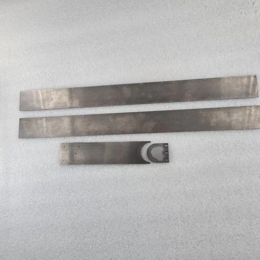
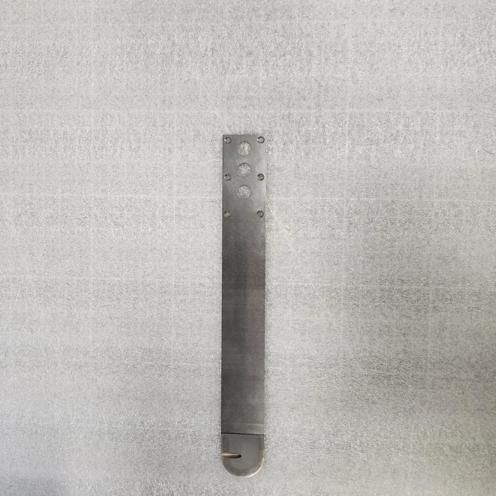
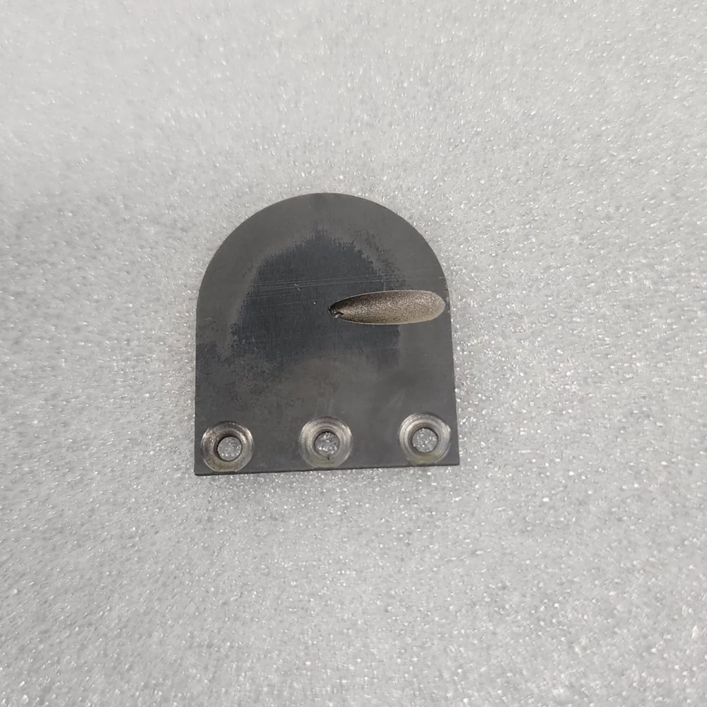
Tungsten Carbide Machining
What we agree before any finishing step starts. Route, tolerance and grade are confirmed per part.
| Capability | Specification |
|---|---|
| Material | Cemented tungsten carbide (WC-Co), most often YG8 or YG15; other grades per your drawing. Tungsten heavy alloy is a different material on a separate page |
| Typical tolerance | ±0.05 mm typical on finished faces; the requirement on your drawing governs, and a tighter figure is quoted against the feature rather than assumed |
| Processes | All three finishing routes are run here — grinding, wire EDM and diamond milling; the one that fits the grade, geometry and batch size is chosen per part |
| Features made | Through holes, countersinks, slots and lens-shaped cut-outs, profiled outlines, stepped and domed faces |
| Section | Flat parts up to 300 × 600 mm; thin strips and plates are limited by edge quality and workholding, checked on the drawing |
| Typical use | Wear strips and guide rails · sealing and valve faces · orifice and nozzle parts · fixture and gauge contacts |
| Edge condition | Inspected as its own feature; reported on the first article |
| Inspection | Zeiss CMM on critical dimensions; first-article inspection report on request |
| Lead time | Confirmed at quotation — the finishing route sets it, not a standard machining slot |
What we will not pretend to know before we see the drawing
Carbide is not a material where one figure covers everything. ±0.05 mm is what a finished face routinely holds; which of the three routes a part takes — grinding, wire EDM or diamond milling — depends on the grade, the section thickness and how the blank arrives — sintered to near-net shape or cut from stock. So the route is stated per part, in writing, before the order, and so is any dimension that has to sit tighter than the figure above. If a drawing asks for something the material cannot hold, we say so at that point rather than at first article.
From Drawing to Delivered Part
Fewer steps than steel, and each one decided before the part is touched.
Submit & Review
Send the drawing, the carbide grade and the blank form (sintered to size, or cut from stock). Engineers check edge access, thin sections, how the part is held and where the finish has to stop.
Quote & Route Plan
The quote names the finishing route and the inspection plan for that part — so the price reflects how the geometry is actually produced, not a generic machining hour.
Make & Inspect
Finishing to the agreed route, then dimensional checks on the critical features and an explicit look at the working edges.
Deliver & Support
Parts are packed to protect edges, not just to fill a box, and repeat orders run from the same route and program.
Frequently asked questions
Request a Quote
Tell us about your program. The fields below help our engineering team prioritize recurring, long-term supply programs with equipment manufacturers.
What happens after you send your files
- Within 1 business day an engineer — not a salesperson — reviews your drawings and replies.
- DFM review: tolerances, material and risk flags, before any cutting begins.
- Your quote includes a material-verification plan: grade, EN/DIN check, certificate strategy.
Critical features are verified in house · material chemistry confirmed by spectrometer · EN 10204 3.1 certificates available.
Prefer email? Write to us directly at info@prototech-machining.com
Drawings and CAD files are used only to quote and manufacture your parts. They are not shared with third parties, and we sign an NDA on request — even before you send anything.
Our form captures production type, annual quantity and project status up front — so we can focus engineering resources on long-term supply relationships, not one-off inquiries.
Talk to our team about special materials, tolerances or a failed-supplier recovery before you send drawings.